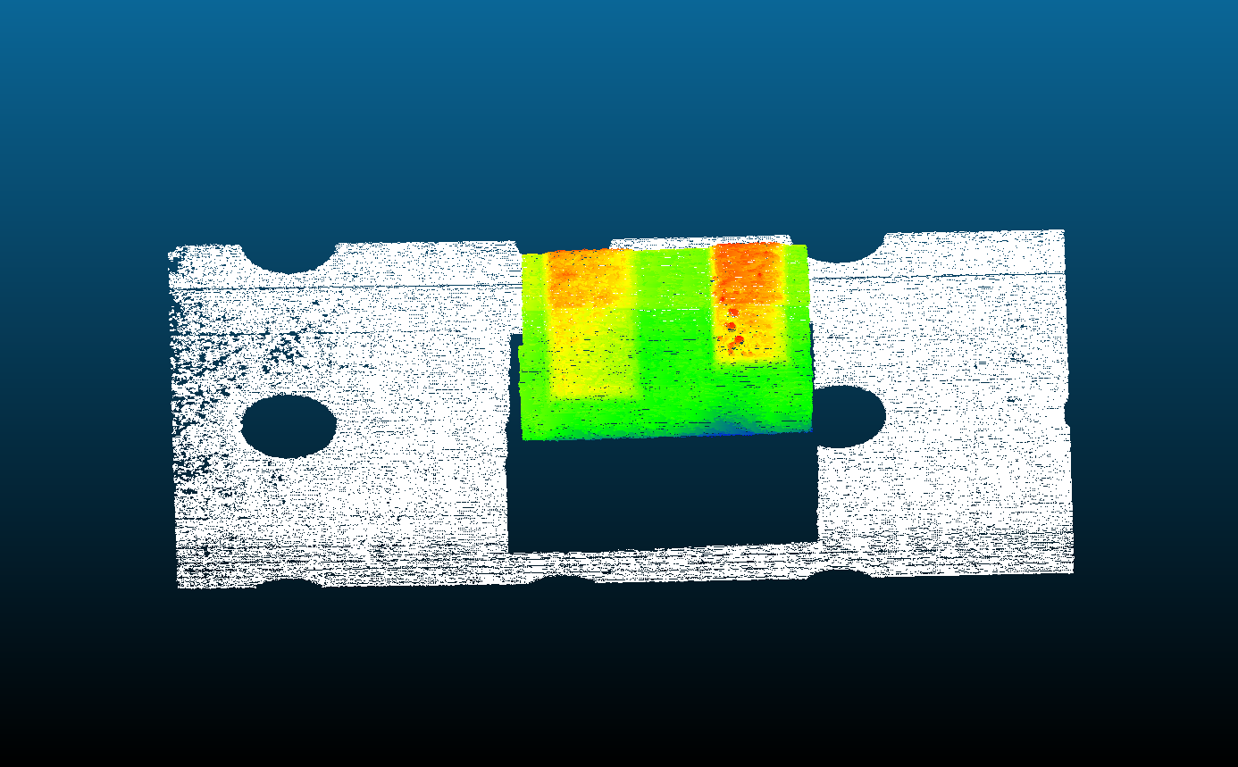
The purpose of 3D geometrical monitoring is to obtain at each time instant the 3D point cloud (i.e., geometric information about the tracks resulting from the LMD process) in robot coordinates. This has to be accomplished on-line, independently of the speed of movement (within the practical limits of the process) and without the need to apply any restrictions to the possible paths.
 |
Software shared in OpenLMD is intended for research, even so, it is being tested on an industrial facility. |
On-line scanning without robot movement restrintions.
Introduction
The 3D monitoring system provides an on-line scanning solution based on the triangulation principle and integrated with the laser head.
A 2D camera, a laser stripe, and the coupling element are only the hardware components required to perform the scanning functions based on triangulation. To improve the overall performance of the solution a NIR camera from IDS is used, because the sensor of this camera provides an improved sensitivity (about 60%) in the range of the laser wavelength (660nm). This sensitivity is a key factor to minimize the exposition time, reducing the distortion error caused by the movement in the image.

The system combines 3D triangulation and instantaneous robot position monitoring (see figure above) to register the 3D point cloud without robot movement restrictions. The following elements can be identified:
- Two drivers connected to the LMD robotized cell, one for Ethernet communication with the robot ROS driver, and another for Gigabit Ethernet image acquisition from the camera.
- Robot State Publisher, a standard ROS node allowing instantaneous robot pose to be determined.
- Peak Finder, which locates in an image the 2D laser profile, i.e., the points illuminated by the laser stripe.
- Robot Pose Tool-Camera, which computes the instantaneous camera pose from the data provided by both the State Publisher and the transformation that relates the pose of the camera with that of the robot tool, implemented as part of the Calibration process.
- Laser Triangulation, which transforms the 2D laser profile (image coordinates) in 3D (real) camera coordinates.
- Camera Pose + 3D Profile + (timestamp), which derives for each time instant (i.e., for each captured image) the 3D point cloud in robot coordinates.
Contact
Verónica Panadeiro-Castro (veronica.panadeiro@aimen.es)
Baltasar Lodeiro-Señarís (baltasar.lodeiro@aimen.es)
Jorge Rodríguez-Araújo (jorge.rodriguez@aimen.es)
Copyright 2016-2017 - AIMEN Technology Center